Circuit Schematic Diagram / Snc1p - Alarm circuit for drinking water.. Also called wiring diagrams or circuit diagrams, these diagrams show how the different components of a circuit are connected.in these diagrams, lines represent connecting wires, while other elements like resistors, lamps, and switches are represented by. Circuit diagram.org also provides a full educational system to students new to electronics. A theremin circuit shown in the schematic diagram below use different method to control the pitch. Figure 3 is an example of an electronic schematic diagram. Electronic schematics use symbols for each component found in an electrical circuit, no matter how small.
Seamless circuit design for your project. Electronic schematics use symbols for each component found in an electrical circuit, no matter how small. Circuito.io is an online tool for designing electronic circuits. Think of it this way; Basics 14 aov schematic (with block included) basics 15 wiring (or connection.
Figure 1 3 A Simple Schematic Diagram Tinkercad from csg-prd.tinkercad.com These free electronic circuits are properly tested and can be found with schematic diagrams, breadboard image or pcb, a detailed explanation of working principle and a demonstration video. A circuit diagram, or a schematic diagram, is a technical drawing of how to connect electronic components to get a certain function. Schematic diagrams are typically associated with electrical circuits. 12v to 24v dc converter power supply circuit diagram. Determine if everyday objects are conductors or insulators, and take measurements with an ammeter and voltmeter. Basics 14 aov schematic (with block included) basics 15 wiring (or connection. Explore simple electronics circuits and mini projects ideas. If you are new to electronics, you are a student or an electronic.
The schematics do not show placement or scale, merely function and flow.
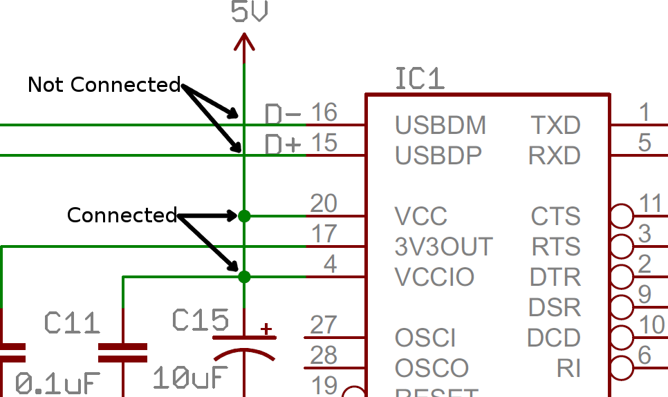
Circuit schematic diagram > radio. The schematics do not show placement or scale, merely function and flow. After seeing a few circuit diagrams, you'll quickly learn how to distinguish the different symbols. Circuit diagrams or schematic diagrams show electrical connections of wires or conductors by using a node as shown in the image below. The schematics do not show placement or scale, merely function and flow. Radio 4 transistor fm tracking transmitter. No additional notes for this tracking transmitter diagram, try to discover this circuit by yourself. The schematic for the em theremin. Each electronic component has a symbol. 12v to 24v dc converter power supply circuit diagram. Experiment with an electronics kit! A node is simply a filled circle or dot. Determine if everyday objects are conductors or insulators, and take measurements with an ammeter and voltmeter.
From this, the actual workings of a piece of electronic equipment can be determined. One of the most essential skills for an electrical engineer is the ability to read and create schematics. This tutorial should turn you into a fully literate schematic reader! Dell wistron db13 disschematic circuit diagram Below is a diagram of a circuit with a switch, two resistors, and a battery.
How To Read A Schematic Learn Sparkfun Com from cdn.sparkfun.com Seamless circuit design for your project. 12v to 24v dc converter power supply circuit diagram. The schematic for the em theremin. From this, the actual workings of a piece of electronic equipment can be determined. View the circuit as a schematic diagram, or switch to a lifelike view. Every symbol or sign represents various meaning about the topi. These two different types of circuit diagrams are called pictorial (using basic images) or schematic style (using industry standard symbols). Figure 3 is an example of an electronic schematic diagram.
By anne mahaffey download pdf.
This is the circuit diagram of drinking water alarm based a small water sensor by using aluminium foil and plastic foil, and connected to a very simple alarm based a 555 ic timer. The schematics do not show placement or scale, merely function and flow. Download nokia schematic circuit diagrams. Basics 13 valve limit switch legend : Schematics are our map to designing, building, and troubleshooting circuits. From this, the actual workings of a piece of electronic equipment can be determined. Explore simple electronics circuits and mini projects ideas. A circuit diagram (electrical diagram, elementary diagram, electronic schematic) is a graphical representation of an electrical circuit.a pictorial circuit diagram uses simple images of components, while a schematic diagram shows the components and interconnections of the circuit using standardized symbolic representations. Seamless circuit design for your project. Circuit schematic diagram > radio. This tutorial should turn you into a fully literate schematic reader! Determine if everyday objects are conductors or insulators, and take measurements with an ammeter and voltmeter. The schematics do not show placement or scale, merely function and flow.
Explore simple electronics circuits and mini projects ideas. After seeing a few circuit diagrams, you'll quickly learn how to distinguish the different symbols. Symbol usage depends on the audience viewing the diagram. A circuit drawing allows you to visualize how components of a circuit are laid out. Circuit diagram.org provides free best quality and good designed schematic diagrams, our diagrams are free to use for all electronic hobbyists, students, technicians and engineers.
How To Draw Schematic Diagrams from opencircuitdesign.com This is the circuit diagram of drinking water alarm based a small water sensor by using aluminium foil and plastic foil, and connected to a very simple alarm based a 555 ic timer. Lines connect fuses, switches, capacitors, inductors, and more. Circuit diagrams are widely used for circuit design, construction, and maintenance of electrical and electronic equipment. Basics 8 aov elementary & block diagram : Smartdraw comes with thousands of detailed electrical symbols you can drag and drop to your drawings and schematics. The time for water supply is determined by administration…. Electronic schematics use symbols for each component found in an electrical circuit, no matter how small. Circuit diagrams or schematic diagrams show electrical connections of wires or conductors by using a node as shown in the image below.
Electronic schematics use symbols for each component found in an electrical circuit, no matter how small.
A basic element of circuit design. The schematic for the em theremin. These free electronic circuits are properly tested and can be found with schematic diagrams, breadboard image or pcb, a detailed explanation of working principle and a demonstration video. No additional notes for this tracking transmitter diagram, try to discover this circuit by yourself. The following diagram is the fm tracking transmitter based on 4 transistors. Electronic schematics use symbols for each component found in an electrical circuit, no matter how small. Experiment with an electronics kit! Which of the following shows the correct pathways for the conventional current and electron current ? These two different types of circuit diagrams are called pictorial (using basic images) or schematic style (using industry standard symbols). Schematics are our map to designing, building, and troubleshooting circuits. Radio 4 transistor fm tracking transmitter. A block diagram can provide a clear understanding of how each part operates in conjunction with the others. A circuit diagram is any type of diagram that demonstrates how a circuit operates where the main purpose is the proper wiring of components and their relationship to each other rather than physical location relative to each o.