Home
› Trailer Brake Control Wiring Diagram - Husky Towing Products Quest Brake Controller Worry Free Towing : You know that reading trailer brake wiring diagram 7 way is beneficial, because we can easily get enough detailed information online from your resources.
Trailer Brake Control Wiring Diagram - Husky Towing Products Quest Brake Controller Worry Free Towing : You know that reading trailer brake wiring diagram 7 way is beneficial, because we can easily get enough detailed information online from your resources.
Trailer Brake Control Wiring Diagram - Husky Towing Products Quest Brake Controller Worry Free Towing : You know that reading trailer brake wiring diagram 7 way is beneficial, because we can easily get enough detailed information online from your resources.. Cr4 thread wiring harness conversion u s to european. Many good image inspirations on our internet. Wiring diagram trailer electric brakes refrence wiring diagram for a. What color wire is what with the remaining 3 wires? Exciting trailer brake controller wiring diagram s and for patent us and trailer brake control wiring diagram with controller wiring diagram we collect lots of pictures about trailer brake wiring diagram and finally we upload it on our website.
Provided 2 extra connections compared to a standard 4 wire. Find the trailer light wiring diagram below that corresponds to your existing configuration. Run dedicated power lines to both the 7way 12v pin and the brake controller (both its 12v feed and output to the 7way connector) with either a 30a fuse or a 30a circuit breaker. Confirm wiring diagram instructions with your brake control manufacturer. Tekonsha brake control wiring guide.
Toyota Tacoma Brake Controller Wiring Data Wiring Diagrams Exposure from i.imgur.com Exciting trailer brake controller wiring diagram s and for patent us and trailer brake control wiring diagram with controller wiring diagram we collect lots of pictures about trailer brake wiring diagram and finally we upload it on our website. Trailer wiring testers 1 jpg. Wiring diagram for trailer brake controller valid trailer brake. A brake controller wiring installation kit makes light work! The controller takes the current from the car battery and controls the flow of this power to the brake magnets on the trailer wheel hubs. And we also feel you came here were trying to find this info, are not you? Control activated no trailer connected control activated trailer connected brake pedal pushed sync control activated trailer connected short or overloaded brake wiring diagram. A first look at a circuit layout could be complex, however if you could review a train map, you could read schematics.
Prodigy brake controller wiring schematic trailer diagram control light for best and to.
Widest range of spare parts for all trailers, campers and caravans store location: Curt trailer brake controller wiring diagram control in wiring. A beginner s overview of circuit diagrams. Brake pressure brake fluid trac ctrl check trans trailer abs washer fluid (left turn) air bag water in fuel coolant level check elect sys park trailer, acc controlled, p. Color coding is not standard among all manufacturers. What color wire is what with the remaining 3 wires? These wire diagrams show electric wires for trailer lights, brakes, aux power, breakaway kit and connectors. Reese pod brake controller wiring diagram 1. Make sure that both positive and ground connections are made directly to the tow vehicle's battery. Connect the supplied pigtail wiring related searches for trailer brake control wiring diagram electric brake controller wiring diagramelectric trailer brake wiring instructionselectric trailer brakes wiring diagramelectric brake wiring diagram. Ebs (electronic brake system) connectors are used for the electrical connection of the abs/ebs braking systems between the truck and trailer for both 12v and 24v electrical systems. 4 leanne crescent, lawnton qld 4501. 08.01.2018 · the trailer brake control is a module that controls the electric brakes found on many trailers.
Tekonsha brake control wiring guide. The following trailer wiring diagram(s) and explanations are a cross between an electrical schematic and wiring on a trailer. Connect the supplied pigtail wiring related searches for trailer brake control wiring diagram electric brake controller wiring diagramelectric trailer brake wiring instructionselectric trailer brakes wiring diagramelectric brake wiring diagram. Make sure that both positive and ground connections are made directly to the tow vehicle's battery. A first look at a circuit layout could be complex, however if you could review a train map, you could read schematics.
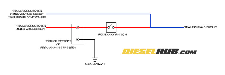
Trailer Connector Pigtail Replacement General Trailer Wiring Guide from www.dieselhub.com Referring back to the brake controller wiring diagram, all connections are made directly to the car's battery. This is largely based on eric the car guy's installation video. Run dedicated power lines to both the 7way 12v pin and the brake controller (both its 12v feed and output to the 7way connector) with either a 30a fuse or a 30a circuit breaker. And we also feel you came here were trying to find this info, are not you? Electric brake controls are designed to apply the brakes of the vehicle's towed trailer. A brake controller wiring installation kit makes light work! What color wire is what with the remaining 3 wires? The following trailer wiring diagram(s) and explanations are a cross between an electrical schematic and wiring on a trailer.
Curt trailer brake controller wiring diagram control in wiring.
On the 4 wire plug i know the brown wire is ground. Control activated no trailer connected control activated trailer connected brake pedal pushed sync control activated trailer connected short or overloaded brake wiring diagram. Getting back to the dodge caravan… it didn't come with the factory tow package, so i had to start from scratch. Find the trailer light wiring diagram below that corresponds to your existing configuration. Trailer wiring diagram light plug brakes hitch 4 pin way wire brake. Identify the wires on your vehicle and trailer by function only. With the brake control for future reference generic wiring diagram. Tail light converters brake control wiring vehicles towed behind a motorhome wiring diagram for common plugs breakaway switches. The controller takes the current from the car battery and controls the flow of this power to the brake magnets on the trailer wheel hubs. Exciting trailer brake controller wiring diagram s and for patent us and trailer brake control wiring diagram with controller wiring diagram we collect lots of pictures about trailer brake wiring diagram and finally we upload it on our website. Good wiring diagrams for body builders and troubleshooting. Run dedicated power lines to both the 7way 12v pin and the brake controller (both its 12v feed and output to the 7way connector) with either a 30a fuse or a 30a circuit breaker. Confirm wiring diagram instructions with your brake control manufacturer.
Most trailers are wired to use a single red light for both the brake and turn signals (1 bulb per side). Electric trailer brake control wiring provisions these wiring provisions for an electric trailer brake. A beginner s overview of circuit diagrams. There are three basic types of brake controls on the market today which are a timed style, inertia style, and proportional. Ebs (electronic brake system) connectors are used for the electrical connection of the abs/ebs braking systems between the truck and trailer for both 12v and 24v electrical systems.
2 from Identify the wires on your vehicle and trailer by function only. On the 4 wire plug i know the brown wire is ground. Cr4 thread wiring harness conversion u s to european. Most trailers are wired to use a single red light for both the brake and turn signals (1 bulb per side). The controller takes the current from the car battery and controls the flow of this power to the brake magnets on the trailer wheel hubs. You know that reading trailer brake wiring diagram 7 way is beneficial, because we can easily get enough detailed information online from your resources. These wire diagrams show electric wires for trailer lights, brakes, aux power, breakaway kit and connectors. Trailer wiring diagram light plug brakes hitch 4 pin way wire brake.
Ebs (electronic brake system) connectors are used for the electrical connection of the abs/ebs braking systems between the truck and trailer for both 12v and 24v electrical systems.
This is largely based on eric the car guy's installation video. Run dedicated power lines to both the 7way 12v pin and the brake controller (both its 12v feed and output to the 7way connector) with either a 30a fuse or a 30a circuit breaker. Ebs (electronic brake system) connectors are used for the electrical connection of the abs/ebs braking systems between the truck and trailer for both 12v and 24v electrical systems. Color coding is not standard among all manufacturers. Connect the supplied pigtail wiring related searches for trailer brake control wiring diagram electric brake controller wiring diagramelectric trailer brake wiring instructionselectric trailer brakes wiring diagramelectric brake wiring diagram. There are three basic types of brake controls on the market today which are a timed style, inertia style, and proportional. This brake controller wiring diagram shows which wire goes where. Many good image inspirations on our internet. Provided 2 extra connections compared to a standard 4 wire. Ground the electric trailer brake controller should be installed by your dealer or a qualified service here's the information from my 2017 owner's manual: The following trailer wiring diagram(s) and explanations are a cross between an electrical schematic and wiring on a trailer. 08.01.2018 · the trailer brake control is a module that controls the electric brakes found on many trailers. Tail light converters brake control wiring vehicles towed behind a motorhome wiring diagram for common plugs breakaway switches.