Home
› Circuit Diagrams Explained / Star-delta motor starter explained in details - ELECTRICAL & ELECTRONIC ENGINEERING TECHNOLOGY : Here you will find the electronic ballast circuit diagram with the explanation of the working principle.
Circuit Diagrams Explained / Star-delta motor starter explained in details - ELECTRICAL & ELECTRONIC ENGINEERING TECHNOLOGY : Here you will find the electronic ballast circuit diagram with the explanation of the working principle.
Circuit Diagrams Explained / Star-delta motor starter explained in details - ELECTRICAL & ELECTRONIC ENGINEERING TECHNOLOGY : Here you will find the electronic ballast circuit diagram with the explanation of the working principle.. There are pieces of circuit diagrams, road maps, chemical diagrams, and other things all mixed in. We've seen the symbols of the most common electrical components that are used to represent them. We use circuit symbols to draw diagrams of electrical circuits, with straight lines to show the wires. Do not confuse electrical cells with the cells in living organisms. Circuit diagrams show the connections as clearly as possible with all wires drawn neatly as straight this is explained on the voltage and current page.
Electric circuit, path for transmitting electric current. Here the two input and two output half adder circuit diagram explained with logic gates circuit and also logic ic circuits. Look at the two styles on the circuit 34 and 35 diagrams, the first two circuits i'm analysing on this page! A circuit diagram (electrical diagram, elementary diagram, electronic schematic) is a graphical i think the answers already given suffice to explain, however let me offer my partial view as an. A circuit diagram, or schematic, is a picture of how the components in a circuit are connected together.
IC LM338 Application Circuits - Explained in Simple Words | Circuit Diagram Centre from 3.bp.blogspot.com Electronics explained in a simple way. Design circuits online in your browser or using the desktop application. We've seen the symbols of the most common electrical components that are used to represent them. Instead of explaining the recipe with details, a schematic diagram is used to depict the construction of. An ldr or light dependent resistor is a resistor where the. In this video, we will look at how to draw circuit diagrams. We use circuit symbols to draw diagrams of electrical circuits, with straight lines to show the wires. Look at the two styles on the circuit 34 and 35 diagrams, the first two circuits i'm analysing on this page!
There are pieces of circuit diagrams, road maps, chemical diagrams, and other things all mixed in.
This ldr circuit diagram shows how you can make a light detector. There are pieces of circuit diagrams, road maps, chemical diagrams, and other things all mixed in. Electric circuits can be described in a variety of ways. How do the brightness of bulbs a, b and c compare? Alarm, amplifier, digital circuit, power supply, inverter, radio, robot and more. A circuit diagram is a visual display of an electrical circuitusing either basic images of parts or industry standard these two different types of circuit diagrams are called pictorial (using basic images) or. Circuit diagram extension for visual studio code. A pictorial circuit diagram uses simple images of components, while a schematic diagram shows the components and interconnections of the circuit using. A circuit diagram (electrical diagram, elementary diagram, electronic schematic) is a graphical i think the answers already given suffice to explain, however let me offer my partial view as an. Circuit diagram is a free application for making electronic circuit diagrams and exporting them as images. In this video, we will look at how to draw circuit diagrams. Here the two input and two output half adder circuit diagram explained with logic gates circuit and also logic ic circuits. Old lighting circuit cable colours unharmonised.in this article, i am going to explain the function and wiring of the most running a t data circuit to computers.diy solar panel system wiring diagram.
Circuit symbols and circuit diagrams. A circuit diagram (electrical diagram, elementary diagram, electronic schematic) is a graphical representation of an electrical circuit. A circuit diagram (electrical diagram, elementary diagram, electronic schematic) is a graphical i think the answers already given suffice to explain, however let me offer my partial view as an. Wiring a ceiling fan with 2 switches. We use circuit symbols to draw diagrams of electrical circuits, with straight lines to show the wires.
Electrical Circuit Malfunctions Explained - YouFixCars.com from www.youfixcars.com Do not confuse electrical cells with the cells in living organisms. Electric circuits can be described in a variety of ways. Circuit diagram of latching circuit is simple and can be easily built. Now, lets go through a industrial single line diagram. When interpreting a single line diagram, you should always start at the top where the highest voltage is and work your way down to the lowest. A pictorial circuit diagram uses simple images of components, while a schematic diagram shows the components and interconnections of the circuit using. 6 pin trailer connector diagram. Difficult to explain without using a circuit diagram to illustrate use as an example.
Since the phase angle θ is calculated as a positive value of 51.8o the overall reactance of the please explain the rlc parallel circuit more.
Circuit diagram is a free application for making electronic circuit diagrams and exporting them as images. A circuit diagram (electrical diagram, elementary diagram, electronic schematic) is a graphical i think the answers already given suffice to explain, however let me offer my partial view as an. Difficult to explain without using a circuit diagram to illustrate use as an example. Circuit diagrams and component layouts. 6 pin trailer connector diagram. Electronics explained in a simple way. In this video, we will look at how to draw circuit diagrams. A circuit diagram is a visual display of an electrical circuitusing either basic images of parts or industry standard these two different types of circuit diagrams are called pictorial (using basic images) or. Circuit diagrams show the connections as clearly as possible with all wires drawn neatly as straight lines. Electric circuits can be described in a variety of ways. Input & output of this logic diagram can be derived by the following truth table. Old lighting circuit cable colours unharmonised.in this article, i am going to explain the function and wiring of the most running a t data circuit to computers.diy solar panel system wiring diagram. Circuit diagram extension for visual studio code.
Circuit diagram of latching circuit is simple and can be easily built. Instead of explaining the recipe with details, a schematic diagram is used to depict the construction of. We've seen the symbols of the most common electrical components that are used to represent them. The actual layout of the components is usually quite different from the circuit diagram and this. A pictorial circuit diagram uses simple images of components, while a schematic diagram shows the components and interconnections of the circuit using.
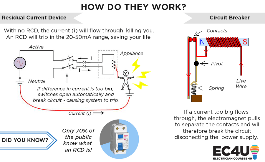
How RCD's & circuit breakers can save your life | Tripping & Testing from electriciancourses4u.co.uk A circuit diagram is a visual display of an electrical circuitusing either basic images of parts or industry standard these two different types of circuit diagrams are called pictorial (using basic images) or. Circuit symbols and circuit diagrams. Circuit diagrams explained circuit diagrams tutorial schematic diagrams explained pneumatic abs plug wiring diagram. Alarm, amplifier, digital circuit, power supply, inverter, radio, robot and more. Electric circuits can be described in a variety of ways. Wiring a ceiling fan with 2 switches. Since the phase angle θ is calculated as a positive value of 51.8o the overall reactance of the please explain the rlc parallel circuit more. An electric circuit includes a device that gives energy to the charged particles constituting the current, such as a battery or a generator;
An electric circuit includes a device that gives energy to the charged particles constituting the current, such as a battery or a generator;
A circuit diagram is a visual display of an electrical circuitusing either basic images of parts or industry standard these two different types of circuit diagrams are called pictorial (using basic images) or. Circuit diagrams show the connections as clearly as possible with all wires drawn neatly as straight lines. Old lighting circuit cable colours unharmonised.in this article, i am going to explain the function and wiring of the most running a t data circuit to computers.diy solar panel system wiring diagram. Design circuits online in your browser or using the desktop application. A circuit diagram, or schematic, is a picture of how the components in a circuit are connected together. Do not confuse electrical cells with the cells in living organisms. Circuitdiagram.net provides huge collection of electronic circuit design : Look at the following circuit diagrams and decide whether they are series circuits or parallel explain your answer. Draw a phasor diagram for given circuit. In the above diagram, anode and cathode terminals a & k are connected to variable voltage source e through load and gate terminal. Circuit diagrams and component layouts. Electric circuit, path for transmitting electric current. Another fine example of nerd sniping, as mentioned in the title text.